Sketchup for Interior Design books

Sketchup for Interior Design books
Now Sketchup 2013 for Interior Designers

Tuesday, October 18, 2011

Curved shapes in Sketchup. Case study of a lighting fixture

Recently, my company was entrusted with some interior renderings for a church. The project is an auditorium with a relatively low ceiling that makes a non inviting space, with fluorescent lights scattered throughout the area, with unattractive colors and crammed with uncomfortable furniture.

The idea of ​​the architect is to turn that space into a pleasant meeting place and replicate the elegance and prestige that currently has the nave of the church. This case study is a perfect example to continue the topic of how to make vaulted ceilings in Sketchup, how to prepare images and textures for use on floors or as wallpapers, or how to create curved lighting fixtures.

All the space was modeled in Sketchup and rendered in 3DMax. In the coming posts I will tell you how we did it. Today I will start with the lighting fixtures.
The picture provided by the architect indicated that the lamps would be like the photo except for the color of the glass that should be white.
We checked the image that had double-curved shade and other curved faces. To simplify our work we decided to use Extrusion Tools plug-in developed by TGI. One of the guidelines that we follow when we create renderings is to keep the geometry as simple as possible with the least number of edges and avoid any unnecessary detail due to distance or point of view will not be seen.
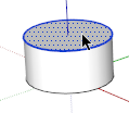
The first step was drawing two concentric circles with 12 sides each instead of the default 24. In this way we could make the edges smoother without need to involve many faces and at the same time to work with 6 sections to recreate the shade.We created a vertical face on which we draw the shade curve and then we copied it at 60 degrees.


Then we copy the outer arc at the top. We delete unnecessary lines and we used the Extrude Edges by Rails. In order we chose the upper curve, the two rails and finally the lower arc for the melting curve. To all the answers we answered no except for smooth edges. The result is as shown in the picture.


Then we copy the outer arc at the top. We delete unnecessary lines and we used the Extrude Edges by Rails. In order we chose the upper curve, the two rails and finally the lower arc for the melting curve. To all the answers we answered no except for smooth edges. The result is as shown in the picture.

Once created the first group we made 5 copies with rotation and then grouped the 6 sections to form the shade.
For the metal frame we drew a rectangle in the XY plane and use Edge Extrude Faces by using the arc as profile. Then we made 5 copies with rotation every 60 degrees and grouped them. Using the Outliner is essential to separate and hide the various groups and subgroups that we created.


For the ring perimeter simply we changed the number of edges of the base circle at 24 and then apply Pull / Push tool. We deleted the entities that we did not need leaving 4 segments of the curve.

Separately we created a prism and the rosette groups to intersect the faces of the ring. We omitted most curved edges to simplify the model. We placed groups on the ring.


After applying Intersect Faces with Selection we deleted the prisms and the intersected faces. We created a component which we rotated and copied. Using Ctrl + erase we removed the joint edges.


Finally we created the center and hangers using Push / Pull and Follow Me.


Monday, September 26, 2011

How to create a shell niche

A few nights ago I was having dinner in a nice Italian restaurant with a neo-classic decoration. A few walls had shell niches that exhibited wonderful sculptures. These niches were exedras - a semicircular recess inside the wall.
The word Niche derives from the Latin nidus or nest. The Italian nicchio for a sea-shell may also be involved, as the traditional decoration for the top of a niche is a scallop shell. I recall a nice piece of art of Filippo Lippi - Madonna - where the trompe-l'oeil niche frames her.
I took a picture with my phone with a very bad light just to remember the image.
I thought it could be a very good example to apply the Extrude tools plugin developed by TGI. After registering you can download them from http://forums.sketchucation.com/viewtopic.php?p=217663#p217663 .
You will also need another plugin called Weld from Smustard that can be downloaded from http://www.smustard.com/script/Weld . All these plugins are free.
Once you have downloaded both tools follow the instructions how to install them.
These tools are a must-to-have for interior designers.
After analyzing the geometry I decided that the option to use was "Extrude Edges by Rails." I had organic forms with double curvature, the front arcs and two curved paths converging at the rear of the exedra.
I followed this procedure:
1. I drew a 12 segments half-circle in the red-green plane. I drew another half-circle in the red-blue plane with the same properties that would be the opening of the niche. I made a third half-circle with an offset at 2” to get a face to work on and to use it in a later step to finish the overall niche.
I exploded the “opening” arc to get separate segments. I divided the second segment into 6 and drew a big arc and two small on each side. I worked with the second segment of the arc because it was above the bottom part of my drawing and was easier for me to work with.
I drew a line from the center point to the base arc to divide it into two parts and work only with the curve that I was going to use as rail. I rotate + copy 15 degrees and 30 degrees, and drew a short arc between the two rails to define the shell focal point.

Next, I erased the construction lines and I joined with Weld the three small arcs of the wedge.

I selected Extrude Edges by Rails from the Extrude toolbar and selected Arc 1 as profile curve, Arc 2 and 3 as rail curves, and Arc 4 as melding-profile.
I reversed faces, erased coplanar edges, smooth edges and erased original curves.
Once the group was created I rotated + copy 11 times every 15 degrees and I made a group. With Intersect Faces > With Selection I divided the front face into two separate ones so I could erase the face covering the niche space to reveal the inside of the niche.
 

Finally I drew a profile in the top edge of the cylinder and I used Follow-Me to create a molding to separate the cylinder from the exedra. ( I could also have used Extrude by Lathe)
To create a fast rendering I applied gold color inside the niche. I imported an alpha-transparent background image “as image” and applied it on a vertical face. I created an Always Face Camera component. I edited the component and erase the vertical face keeping only the image. I placed the Rodin sculpture inside the niche. I turned the edges and profiles off,


I used Pull/Push to create the lower part of the niche and Line to complete missing faces.

Wednesday, August 24, 2011

How to simulate artificial lights without using a rendering plug-in


When it comes to professionals dedicated to an activity such as interior design is likely to refer to people that not only have the latest generation computers but also do not have time to explore other programs to show their ideas. The goal is just to convey their ideas to potential customers, not to become software gurus. What they really need are fast, efficient and time-saving tools as Sketchup. However, my theory is that if I have to spend twice as long to produce a drawing or a rendering that I am able to do by hand it is not worth the use of a computer.

Rendering processes take too much time and not always can be afforded. I've tried several plug-ins for photo-realistic renderings, but unfortunately they require a huge amount of resources from my two-year old laptop. When I have to discuss my ideas with some clients, especially in the early stages I take the 3D model with me. I prepare some scenes with shadows to start my presentation. I also prepare some scenes without shadows to allow me to move around without my computer becoming too slow. This strategy has been very successful to me because my clients become protagonists of my projects and I can engage their emotions in my proposals.

It is a fact that in the interior design field artificial lighting is vital and in Sketchup sun ​​is the only source of illumination. Recreate therefore shining light sources is impossible when using only Sketchup. However, lately I've resorted to these tricks to achieve it.

  1. Once shaped my project which I always group it I select the ceiling and I check off “Cast Shadows” Entity Information dialogue box. Doing this allows the sunlight to come inside my room.
  2. Unless I need to do a shadow study I rarely provide any geographical information to my model. That's why I change the UTC time and day to make the illumination of the sun as vertical as possible to provide more contrasts and expression to my scenes.


To recreate the artificial lighting I do the following:

 1. I create a cone and apply a white, blue or yellow material with translucent properties below 50% in each of the faces. This percentage is very important because higher values ​​cast shadows. I usually set the opacity around 20. I create a component.
 2. I create a second component which is usually an arc. I apply another less translucent material with more intense color properties to simulate the light bulb. I place a vertical line to have an endpoint to grip the component into position when inserted. I place the bulb over the cone.
 3. I make a new component grouping the previous two.
 4. I double-click to enter to the edit mode and select the cone. Using Window> Soften Edges I expose only the faces. I enter to the bulb edit mode but this time I use the Erase + Shift function to hide the arc and lines.
 5. I save my component for further use in my library.
 6. I insert the cone of light in the light fixtures and uncheck the Profiles option from View> Edge Style. If I want to change the tone of the light simply I edit the material and change the base color.
 7. I create my scenes.

Note: The shapes of the light cones are governed by the type of lamps and shades I am using; this is why I keep in my library options for each case.


Thursday, July 14, 2011

How to print in Sketchup with sharp lines and in scale.


I can not seem to print or export my drawings and get crisp clear lines. I tried changing the line weights (only profiles) but it was not helpful. The lines look blue.”

This is just one of the comments I get from readers and students. Perhaps we as instructors are not paying attention to this topic which seems obvious but it is not so. SketchUp has some simple tricks to print images with sharp and clear lines. The problem is that given the simplicity of SketchUp often print tips are given by other people that not necessary have the best knowledge of the different alternatives that the program offers to print. Many times they end up exporting an image and then printing in any photo editing program.

There are many printing options offered in Sketchup. The first thing you should decide is the output quality. By default, the quality of the Print dialog box is set to Draft. Besides the output quality you may decide to make the printing based on vectors or as a raster image.

Alternative 1
To print directly from SketchUp and get defined lines check the option "Use High Accuracy HLR" in the Print dialog box. Using this feature will send the information to the printer to print as vectors instead of pixels. If you use this option please note that it is possible that the start of the printing takes several minutes depending on the complexity of your model. Do not use imported images “as images” because they will not be recognized, use only objects with textures. The option HLR also will not recognize shadows.

Alternative 2
Print your model as a raster image but in order to get sharp lines select "High Definition" in the drop down menu of the Print Quality.

Alternative 3
If your intention is to print or use an image of your model in any photo editor you will need to export an image selecting the adequate resolution for your printing purpose. In this case choose File > Export > 2D Graphic > Options. Remember that a good resolution fro printing is 300 dpi meaning that for every inch that you want to print you have to multiply it by 300. For example, a 8” wide image will have a resolution of 2400 pixels

Alternative 4
If you have the Pro version you can use Layout to insert your drawing. In the SketchUp model tab choose instead of Vector the option Hybrid. In that way you can have the advantages of printing as well as raster and vector. The lines will be crispy while you will be able to print shadows and images.

Alternative 5
A second option in Layout would be to export your file in PDF with an output in High Quality. This alternative allows you to print anywhere or share your file with somebody else.

Printing in Scale
Finally, if you want to print in scale in Sketchup you have to set things properly. Perspectives views can not be printed to scale, so you will need to switch to Parallel Projection and choose any standard view. The scale field in the Print menu is used to scale your model for printing. The first measurement “In the printout” is the measurement of the exported geometry. The second measurement “In Sketchup”, is the actual measurement of the object in real scale. If you want to print in ¼”=1’ you have to enter 1 Inches in the printout field and 4 Feet into Sketchup box. Do not pay attention to the numbers that appear on the Page size option when you are printing in scale.

Printing a perspective
Before printing use Zoom Extents to center your drawing in your window and avoid that your drawing is coming out on several pages. In the Print Size section choose Fit to Page. This option will size the model to fit on a single sheet of paper. It will also tell Sketchup to make your printed page look like your modeling window. Check the Model Extents option to instruct the program to zoom in to make your model fit the printed page.

Wednesday, June 22, 2011

How to make a vaulted ceiling with Sketchup

I had a small project last week that I want to share with you since many of my students always ask me how to make a vaulted ceiling. The following example can help you to design any kind of non-flat ceilings.

In this study case the owner of a house wanted to show some possibilities for two unfinished spaces to a potential buyer. He asked me for a quick rendering where he could show a few ideas without spending too much money. I took some pictures of the space, and took some dimensions. I decided that Sketchup would be perfect for this project.

So I started by drawing a rectangle that included in the width the knee wall spaces on both sides


I used the Push/Pull tool to reach the ridge height. I knew that the slope of the roof was 12:12 and I could verify that on site. I activated the Protractor which I aligned with a vertical face placing it over one corner. I aligned it with the bottom line, and then I rotated. I typed 12:12 that in this particular case is the same as 45 degrees. I repeated the same steps on the opposite corner to get both guide lines.

The knee walls were at 4'-0" from the outside edge, so I drew 2 vertical lines as shown. Then, I completed the roof lines.


With the Pull/Push tool + Ctrl/Opt I pushed inside the shown face to copy it on the back wall. The X-ray mode figure shows what I got.


I copied the same face 3 times where I had the dormer walls helping me with additional guide lines.

I used Push tool to get rid of the outside area where I had no dormers, turned off the X-ray mode and this is what I got.


Since my perspective would be shown from the same place where I took my picture I erase the front wall face instead of using the Section tool to be able to see inside. On the right side I had a roof coming up from a knee wall that formed an L shape with the actual space, so I drew a box on that side. I completed the lines to match the ridge of the main space and the remaining walls.


I turned on the X-ray mode again to draw the missing lines of the dormers, and erase the unwanted ones.


I turned off the X-ray mode and then I used Position Camera tool to get the perspective view that I wanted, and save a scene. I placed windows and doors allowing letting the sunshine in to get a more dramatic scene. I placed furniture, moldings, textures and a few lighting fixtures to get my first rendering attempt using a pencil style.


To add more contrast and brightness I decided to make a fast photorealistic rendering. You can use any plugin on the market. I overlaid both images using Paint.Net and the final result was this one:

Thursday, May 19, 2011

How to create a tufted seat using Sandbox > From Scratch, Smoove a Catmull-Clark Subdivision plugin.

  1. Draw a rectangle of 3x3.
  2. Select Draw > Sandbox > From Scratch. Type ½” for the Grid Spacing.
  3. Pick the first, second and third corners of the rectangle. A mesh will be created. Explode the group.
  4. Open tools> Sandbox> Tools> Smoove. Type 2” for Radius
  5. Place the cursor en the center point. Click. Move the cursor up ¼”.
  6. Select the Erase tool + Ctrl key (Opt in Mac) and smooth edges.
  7. Create a component, copy it along Green and red axes.

Wednesday, May 4, 2011

Google Sketchup for Interior Design & Space Planning. 2nd Edition

The second edition of the book series has just been released. I have included as an upgrade to new version 8, information on plugins suitable for interior design, Intersect with Model exercises, how to create a Queen Ann leg, working with solids, how to use Photo Match to create a piece of furniture, and defining solar orientation with the free version among other small additions.